2000 Cherokee Power Lock Orange violet No Ground Continuity
ANTI-THEFT SYSTEM
1993 Jeep Cherokee
1993 ACCESSORIES & EQUIPMENT Chrysler Corp. Anti-Theft System
Jeep; Cherokee DESCRIPTION & OPERATION
The Vehicle Theft Alarm (VTA) Module is a logic controlled device that monitors vehicle doors, hood, liftgate and ignition tampering. Alarm activates by sounding horn, flashing all external lights and preventing vehicle engine from running. VTA system arms during normal vehicle lock-up procedure (ignition off, all doors locked with power locks). Security light flashes for 15 seconds during arming process. Security light remains lit during arming process if no signal is received from hood switch.
When the VTA is triggered, horn sounds for 3 minutes while flashing all external lights. Headlights, park and taillights continue to flash for an additional 15 minutes after horn stops. VTA system features a tamper alert function that notifies if vehicle has been tampered with by sounding horn 3 times once a front door is unlocked. The VTA will not arm if door is locked using key or manual lock control.
NOTE: If vehicle battery is disconnected and reconnected, the VTA system enters a power up alarm mode. The headlights, park and taillights will flash. The engine will not run. To exit this mode, the VTA system must be disarmed using key or keyless entry transmitter.
TROUBLE SHOOTING
NOTE: VTA system or VTA system self-test will be inoperative if Powertrain Control Module (PCM), has been replaced within last 20 ignition cycles.
1) System operation may be verified by entering self-test
mode. To enter self-test, cycle ignition key to accessory position 3
times, leaving switch in accessory position. Once in self-test mode,
headlights, park and taillights will begin flashing and horn will
sound twice, verifying their operation.
NOTE: Vehicles equipped with VTA are also equipped with
illuminated entry. Unless illuminated entry system is disabled, it is necessary to wait 30 seconds after each door opening or closure before testing can occur.
2) In self-test mode, horn will sound once after each of the
following tests, indicating proper operation.
-
Beginning with all doors closed, open and close each
individual door. The horn will sound each time a door is
opened or closed. Allow one second between opening and
closing. -
Open, then close hood. Horn will sound upon opening and
closing hood. -
Operate power door locks in both directions.
-
Rotate key in both door lock cylinders to unlock position.
Horn will sound as switch closes, and again when it opens.
Allow at least one second between close and open position. -
Cycle ignition switch to RUN position. Horn will sound and
also take VTA out of self-test mode. -
Activate remote keyless entry in both lock and unlock
directions.
-
Horn not sounding after any of the above operations
indicates a switch failure, lack of input signal to VTA module or
internal failure of module. -
Check for continuity at switch. Check for open or shorted
wire between switch and alarm module. See appropriate wiring diagram
in the WIRING DIAGRAMS article in the ENGINE PERFORMANCE section.
Check if PCM has been replaced. When PCM is replaced, it is necessary
to cycle ignition switch through 20 engine starts to initialize
system. -
Whenever a VTA system malfunction occurs, verify wire
harness is properly connected to all connectors before starting normal
diagnosis and repair procedures. If security lamp comes on and remains
on after ignition is turned on, CCD bus communication signal with PCM
has been lost.
CONNECTOR IDENTIFICATION
CONNECTOR IDENTIFICATION DIRECTORY TABLE
Connector Go to Figure
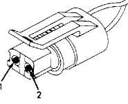
Front Door Key Cylinder Switch See Fig. 1.
Liftgate Key Cylinder Switch See Fig. 2.
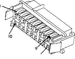
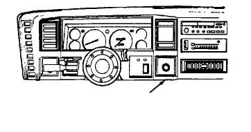
Mechanical Instrument Cluster See Fig. 3.
Powertrain Control Module See Fig. 4.
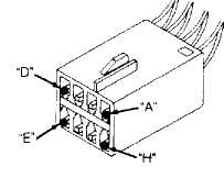
Remote Keyless Entry Module See Fig. 5.
Vehicle Fuse Block See Fig. 6.
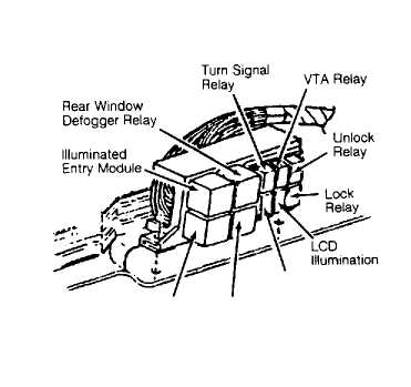
Vehicle Relay Center See Fig. 7.
Vehicle Theft Alarm Module See Fig. 8.
93F75874
Fig. 1: Identifying Front Door Key Cylinder Switch Connector Courtesy of Chrysler Corp.
 2 3-
2 3-
93G75875
Fig. 2: Identifying Liftgate Key Cylinder Switch Connector Courtesy of Chrysler Corp.
9.╪75876 18
Fig. 3: Identifying Mechanical Instrument Cluster Connector Courtesy of Chrysler Corp.
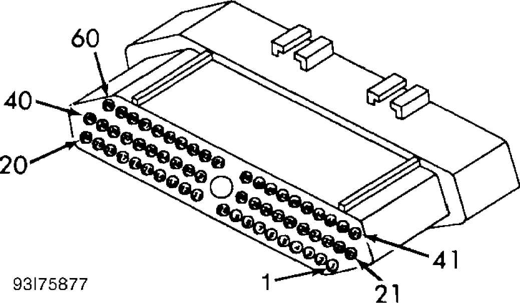
Fig. 4: Identifying Powertrain Control Module Connector Courtesy of Chrysler Corp.
93175878
Fig. 5: Identifying Remote Keyless Entry Module Connector Courtesy of Chrysler Corp.
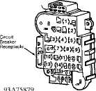
Fig. 6: Identifying Vehicle Fuse Block Courtesy of Chrysler Corp.
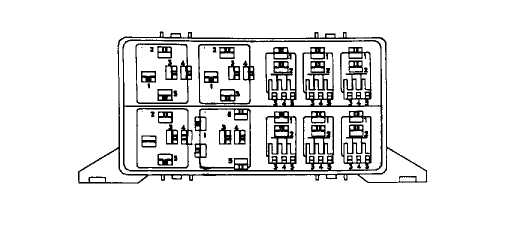
RELAY BLOCK (Mounted Behind Glove Box)
93╧75880
Fig. 7: Identifying Vehicle Relay Center Courtesy of Chrysler Corp.
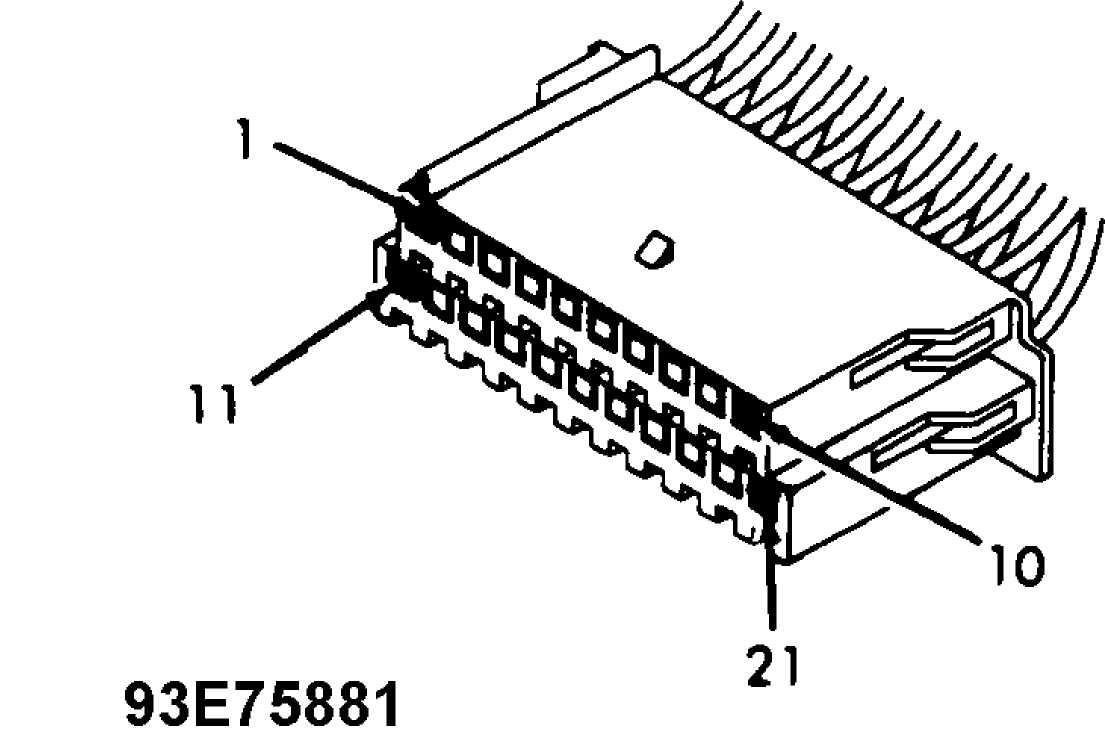
Fig. 8: Identifying Vehicle Theft Alarm Module Connector Courtesy of Chrysler Corp.
TESTING
NOTE: In the following tests, illustrations are courtesy of
Chrysler Corp. For connector terminal identification, see the CONNECTOR IDENTIFICATION table. For wiring diagrams, the appropriate chassis wiring diagram in WIRING DIAGRAMS article in ENGINE PERFORMANCE section.
CAUTION: Always turn ignition switch to OFF position prior to
NOTE:
disconnecting or connecting any module connector. Once connector is disconnected, ignition can be turned on.
There are no diagnostic or trouble codes for Vehicle Theft Alarm system. Only symptom diagnosis and repair are provided by the manufacturer.
USING DRB-II
NOTE: Although other scan testers are available, manufacturer recommends using DRB-II (Diagnostic Readout Box II) to diagnose system.
WARNING: DO NOT probe connector with an ohmmeter unless specifically instructed in testing procedure. There is a possibility of air bag deployment.
Ensure DRB-II is connected to CCD data link connector located in behind dash on right side of steering column. See Fig. 9. Ensure correct cartridge is installed in DRB-II for vehicle and system being diagnosed. Menu selections will vary depending on vehicle and system being diagnosed. Follow DRB-II screen prompts to actuate, adjust, monitor, reset, test and diagnose system as necessary.
DRB-II is grounded through CCD data link connector, only one volt-ohmmeter test lead is required when using volt-ohmmeter option. DRB-II volt-ohmmeter should only be used when self-diagnostic tests require the use of this option.
If DRB-II has a blank screen or displays RAM TEST FAILURE, CARTRIDGE ERROR, KEY PAD TEST FAILURE, LOW BATTERY or HIGH BATTERY, this indicates a DRB-II failure. To diagnose and correct these conditions, see BODY CONTROL COMPUTER - VEHICLE COMMUNICATIONS article in ENGINE PERFORMANCE.
 CCD DATA LINK CONNECTOR
(Mounted Behind Dash, Right Side Of Column)
93C75871
Fig. 9: Identifying Location Of CCD Data Link Connector Courtesy of Chrysler Corp.
TEST 1A - TESTING SYSTEM FUNCTION
NOTE: For connector terminal identification, refer to the CONNECTOR IDENTIFICATION table. For appropriate wiring diagram, see appropriate chassis wiring diagram in the WIRING DIAGRAMS section.
-
Connect DRB-II to data link connector. See Fig. 9. If DRB-
II displays SELECT SYSTEM, select VTA MODULE. If DRB-II is blank or
displays anything other than SELECT SYSTEM, see BODY CONTROL COMPUTER
- VEHICLE COMMUNICATIONS article in the ENGINE PERFORMANCE section. -
If after selecting VTA MODULE the DRB-II displays NO
RESPONSE, go to TEST 2A. If after selecting VTA MODULE the DRB-II
screen does not display NO RESPONSE, disconnect the illuminated entry
module. See Fig. 10. Ensure all doors, hood and liftgate are fully
closed.
 H/Lamp
,_,�,- i Rela y < ECE )
Horn Relay power Antenna
RELAY CENTER (Under Glove Box)
93F75882 Fig. 10: Identifying Relay Center Location
-
If security light flashes constantly, go to TEST 3A. If
security light does not flash, switch VTA status to diagnostic using
DRB-II. If DRB-II does not display TURN IGNITION KEY TO ACC. POSITION,
go to TEST 4A. If DRB-II displays TURN IGNITION KEY TO ACC. POSITION,
turn ignition switch to ACC. position. -
If DRB-II displays NO RESPONSE after turning key to ACC.
position, go to TEST 5A. If after turning key to ACC. position horn
does not sound, go to TEST 6A. If horn does sound, check if security
light is flashing. If security light is flashing, check if park and
headlights are flashing. -
Go to TEST 7A if security light is not flashing. Go to
TEST 8A if exterior lights are not flashing. If exterior lights are
flashing, turn ignition off and open left front door. Close door. If
horn does not sound, go to TEST 9A. -
If horn does sound, open right front door. Close door. If
horn does not sound, go to TEST 9A. If horn does sound, open right
rear door. Close door. If horn does not sound, go to TEST 9A. If horn
does sound, open left rear door. Close door. If horn does not sound,
go to TEST 9A. -
If horn does sound, open hood. Close hood. If horn does
not sound, go to TEST 10A. If horn does sound, open liftgate. Close
liftgate. If horn does not sound, go to TEST 11A. If horn does sound,
push power door lock switch to LOCK position. -
If horn does not sound, go to TEST 12A. If horn does
sound, push power door lock switch to UNLOCK position. If horn does
not sound, go to TEST 13A. If horn does sound, rotate key in left
front door lock to UNLOCK position. If horn does not sound, proceed to
TEST 14A. -
If horn does sound, rotate key in right front door lock to
UNLOCK position. If horn does not sound, go to TEST 15A. If horn does
sound, rotate key in liftgate to UNLOCK position. If horn does not
sound, go to TEST 16A.
-
If horn does sound, turn ignition on. If horn does not
sound, go to TEST 4A. If horn does sound, read vehicle theft alarm
status with DRB-II. If the DRB-II does not display CURRENT MODE
DISARMED, go to TEST 1B. If DRB-II does display CURRENT MODE DISARMED,
DRB-II screen should display ENGINE CONTROLLER: 1) NO RESPONSE, 2) NO
RESPONSE ?. If message is displayed, go to TEST 17A. -
If DRB-II displays the message, ENGINE CONTROLLER: 1) OK
TO RUN ARM VTA, 2) OK TO RUN ENGINE ?, go to TEST 18A if malfunction
is caused by keyless entry, arm or disarm. If message is not
displayed, replace Powertrain Control Module (PCM). -
If keyless entry is working properly, determine if engine
controller has been replaced. If engine controller has not been
replaced, system is functioning properly. Engine has to cycle through
20 ignition starts before VTA becomes operational (assembly plant
alarm override feature).
TEST 1B - TESTING SYSTEM FUNCTION
NOTE: For connector terminal identification, refer to the CONNECTOR IDENTIFICATION table. For appropriate wiring diagram, see appropriate chassis wiring diagram in the WIRING DIAGRAMS section.
Ensure ignition is off. Turn left door lock to UNLOCK
position and turn ignition on. Using DRB-II, read VTA status. If DRB-II displays CURRENT MODE DISARMED, system is functioning properly. Perform TEST VER-1. If screen does not display CURRENT MODE DISARMED, replace VTA module. Perform TEST VER-1.
TEST 2A - REPAIRING NO RESPONSE
NOTE: For connector terminal identification, refer to the CONNECTOR IDENTIFICATION table. For appropriate wiring diagram, see appropriate chassis wiring diagram in the WIRING DIAGRAMS section.
1) Ensure ignition switch is off. Disconnect VTA module. See Fig. 11. Using DRB-II in ohmmeter mode, test system ground circuit for resistance at VTA module connector.
 Controller Antilock Brake
Vehicle Theft Alarm Module
(Under Instrument Panel, Right Of Steering Column)
93G75883 Fig. 11: Identifying Vehicle Theft Alarm Location
-
Check resistance at terminal No. 21 (Black wire). If
resistance is more than 0-15 ohms, repair open circuit. Perform TEST
VER-1. If resistance is less than 0-15 ohms, turn ignition on. -
Using DRB-II in voltmeter mode, check voltage at terminal
No. 8 (Dark Blue/White wire) of VTA module connector. If voltage is
less than 10 volts, go to TEST 2B. If voltage is more than 10 volts,
check ignition voltage at terminal No. 12 (Dark Blue wire). If voltage
is less than 10 volts, go to TEST 2C. If voltage is more than 10
volts, disconnect DRB-II. -
Using external ohmmeter, check resistance between pin No.
4 (Violet/Brown wire) of CCD data link connector and terminal No. 9
(Violet/Brown wire) of VTA module connector. If resistance is more
than 5 ohms, repair open circuit. Perform TEST VER-1. If resistance is less than 5 ohms, check resistance between pin No. 3 (White/Black wire) of CCD data link connector and terminal No. 10 (White/Black wire) of VTA module connector. If resistance is more than 5 ohms, repair open circuit. Perform TEST VER-1. If resistance is less than 5 ohms, replace VTA module. Perform TEST VER-1.
TEST 2B - REPAIRING NO RESPONSE
NOTE: For connector terminal identification, refer to the CONNECTOR IDENTIFICATION table. For appropriate
wiring diagram, see appropriate chassis wiring diagram in the WIRING DIAGRAMS section.
-
Remove fuse No. 4 from fuse block and inspect. If fuse is
open (NG), check resistance between terminal No. 8 (Dark Blue/ White
wire) of VTA module connector using DRB-II. If resistance is less than
5 ohms, repair shorted wire. If resistance is more than 5 ohms,
replace No. 4 fuse. Perform TEST VER-1. -
If No. 4 fuse is good when removed, check voltage feed
circuit with DRB-II. Connect DRB-II to voltage feed terminal of No. 4
fuse (right side of connector) receptacle. If voltage is less than 10
volts, repair open circuit between fuse receptacle and terminal No. 8
(Dark Blue/White wire) of VTA module connector. Perform TEST VER-1. If voltage is more than 10 volts, repair open circuit between terminal No. 12 (Dark Blue wire) of VTA module connector and terminal No. 4
(Violet/Brown wire) of wiper circuit breaker receptacle of fuse block. Perform TEST VER-1.
TEST 2C - REPAIRING NO RESPONSE
NOTE: For connector terminal identification, refer to the CONNECTOR IDENTIFICATION table. For appropriate wiring diagram, see appropriate chassis wiring diagram in the WIRING DIAGRAMS section.
1) Remove wiper circuit breaker from fuse block. Using DRB-
II, check voltage at ignition voltage feed, terminal No. 4
(Violet/Brown wire) of circuit breaker receptacle. If voltage is less
than 10 volts, repair open ignition voltage feed circuit (Violet/Brown wire). Perform TEST VER-1.
-
If voltage is more than 10 volts, check circuit resistance
with DRB-II. Check resistance at terminal No. 12 (Dark Blue wire) of
VTA module connector. If resistance is less than 5 ohms, repair
ignition voltage feed circuit (Dark Blue wire) for short to ground.
Replace wiper circuit breaker. Perform TEST VER-1. -
If resistance is more than 5 ohms, check resistance
between terminal No. 12 (Dark Blue) of VTA module connector and
terminal No. 2 of circuit breaker receptacle of fuse block. If
resistance is less than 5 ohms, replace circuit breaker. If resistance
is more than 5 ohms, repair open ignition feed circuit (Dark Blue
wire). Perform TEST VER-1.
TEST 3A - REPAIRING SECURITY LIGHT FLASHING CONSTANTLY
NOTE: For connector terminal identification, refer to the CONNECTOR IDENTIFICATION table. For appropriate wiring diagram, see appropriate chassis wiring diagram in the WIRING DIAGRAMS section.
1) Disconnect VTA module. See Fig. 11 in TEST 2A. Using DRB- II, check voltage at arm sense terminal No. 6 (Pink/Orange wire) of VTA module connector. If voltage is less than one volt, replace VTA module. Perform TEST VER-1. If voltage is more than one volt, disconnect remote keyless entry module. See Fig. 12.
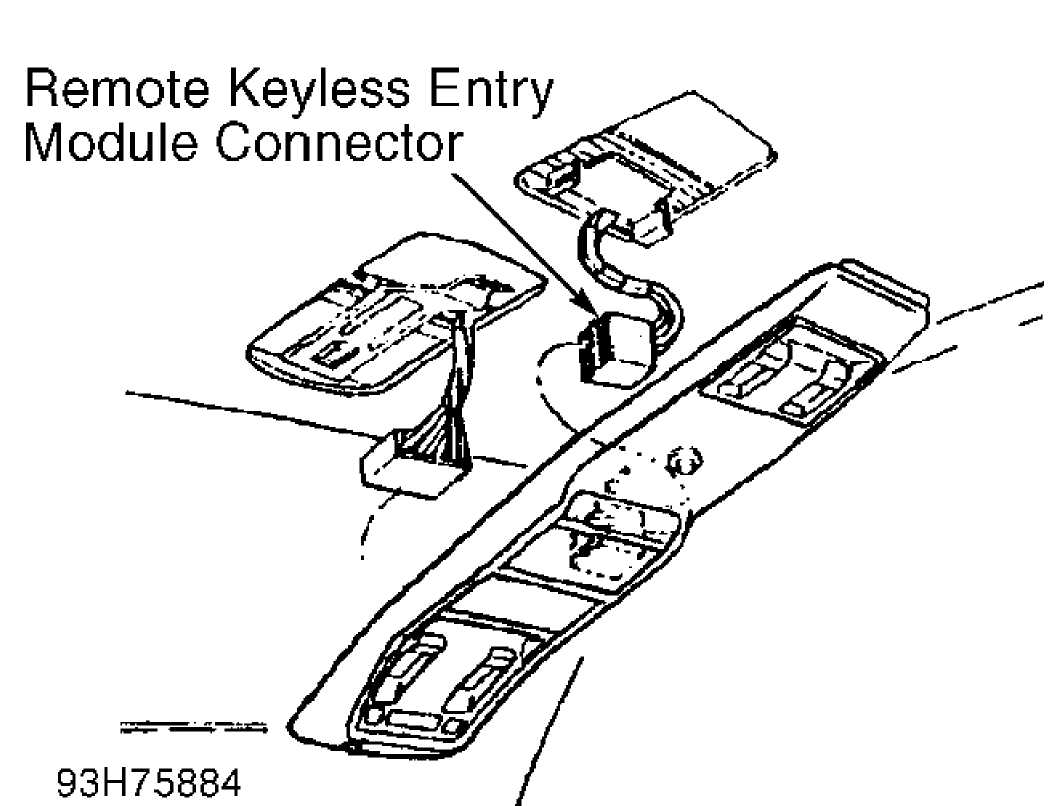
Fig. 12: Identifying Remote Keyless Entry Module Location
2) Using DRB-II, check voltage at arm sense circuit terminal No. 6 (Pink/Orange wire). If voltage is more than one volt, repair shorted arm sense (Pink/Orange wire). Perform TEST VER-1. If voltage is less than one volt, replace remote keyless entry module. Perform TEST VER-1.
TEST 4A - REPAIRING IGNITION INPUT CIRCUIT
NOTE: For connector terminal identification, refer to the CONNECTOR IDENTIFICATION table. For appropriate wiring diagram, see appropriate chassis wiring diagram in the WIRING DIAGRAMS section.
-
Ensure ignition is turned off. Disconnect VTA module. Turn
ignition on. Using DRB-II, check voltage at terminal No. 8 (Dark
Blue/White wire) of VTA module connector. If voltage is more than 10
volts, replace VTA module. Perform TEST VER-1. -
If voltage is less than 10 volts, remove No. 4 fuse and
inspect. If fuse is open (NG), check resistance at terminal No. 8
(Dark Blue/White wire) of VTA module connector with DRB-II. If
resistance is less than 5 ohms, repair ignition voltage feed circuit
terminal No. 8 (Dark Blue/White wire) shorted to ground. Perform TEST
VER-1. -
If resistance is more than 5 ohms, replace fuse. If fuse
No. 4 is not open (good), check voltage feed circuit at fuse No. 4
(right side of receptacle) with DRB-II. If voltage is less than 10 volts, repair open circuit between fuse receptacle and terminal No. 8
(Dark Blue/White wire) of VTA module connector. Perform TEST VER-1. If voltage is more than 10 volts, repair open circuit between pin No. 12
(Dark Blue wire) of VTA module connector and terminal No. 4
(Violet/Brown wire) of wiper circuit breaker of fuse block. Perform TEST VER-1.
TEST 5A - REPAIRING IGNITION INPUT CIRCUIT
NOTE: For connector terminal identification, refer to the CONNECTOR IDENTIFICATION table. For appropriate wiring diagram, see appropriate chassis wiring diagram in the WIRING DIAGRAMS section.
1) Ensure ignition is off. Disconnect VTA module. Turn
ignition on. Using DRB-II, check voltage at terminal No. 12 (Dark Blue wire) of VTA module connector. If voltage is more than 10 volts, replace VTA module. Perform TEST VER-1. If voltage is less than 10 volts, remove wiper circuit breaker.
-
Using DRB-II, check voltage at terminal No. 4 (Light
Green/Black wire) of circuit breaker receptacle. If voltage is less
than 10 volts, repair open voltage feed circuit (Light Green/Black
wire). If voltage is more than 10 volts, check resistance at terminal
No. 2 (Light Green/Black wire) of wiper circuit breaker receptacle and
terminal No. 12 (Dark Blue wire) of VTA module connector. -
If resistance is less than 5 ohms, repair shorted circuit.
Perform TEST VER-1. Replace circuit breaker. If resistance is more
than 5 ohms, repair open voltage feed circuit. Perform TEST VER-1.
TEST 6A - REPAIRING HORN CIRCUIT
NOTE: For connector terminal identification, refer to the CONNECTOR IDENTIFICATION table. For appropriate wiring diagram, see appropriate chassis wiring diagram in the WIRING DIAGRAMS section.
1) Push horn button on steering wheel. If horn sounds,
disconnect VTA module. Using DRB-II, check voltage at terminal No. 5
(Black/Red wire) of VTA module connector. If voltage is less than 10 volts, repair open horn relay control circuit (Black/Red wire).
-
If voltage is more than 10 volts, check voltage on fused
battery feed circuit, terminal No. 2 (Gray/Pink wire) of VTA module
connector. If voltage is less than 10 volts, repair open fused battery
voltage feed wire. If voltage is more than 10 volts, replace VTA
module. Perform TEST VER-1. -
If horn did not sound when pushing steering wheel button,
disconnect VTA module. Connect jumper wire between horn relay control
wire (terminal No. 5 of VTA module connector) and ground. If horn
sounds, replace VTA module. See the appropriate STEERING COLUMN
SWITCHES article in the ACCESSORIES/SAFETY EQUIP section for horn
button/wiring repair. -
If horn does not sound, remove horn relay. See Fig. 10 in
TEST 1A. Using DRB-II, check fused battery feed voltage at terminal
No. 1 of horn relay receptacle. If voltage is less than 10 volts, go
to TEST 6B. -
If voltage is more than 10 volts, check voltage at fused
battery feed terminal No. 5 (Gray/Pink wire) of horn relay receptacle.
If voltage is less than 10 volts, repair open fused battery feed
circuit (Gray/Pink wire). Perform TEST VER-1. -
If voltage is more than 10 volts, check resistance between
terminal No. 2 (Black/Red wire) of horn relay receptacle and terminal
No. 5 (Black/Red wire) of VTA module connector with external ohmmeter.
If resistance is more than 5 ohms, repair open horn control circuit (Black/Red wire). Perform TEST VER-1 .
7) If resistance is less than 5 ohms, connect a jumper wire between terminals No. 1 (Pink/Light Green wire) and No. 4 (Dark Green/Red wire) of horn relay receptacle. If horn sounds, replace horn relay. Perform TEST VER-1. If horn does not sound, repair open horn feed circuit (Dark Green/Red wire). Perform TEST VER-1.
TEST 6B - REPAIRING HORN CIRCUIT
NOTE: For connector terminal identification, refer to the CONNECTOR IDENTIFICATION table. For appropriate wiring diagram, see appropriate chassis wiring diagram in the WIRING DIAGRAMS section.
-
Remove and inspect fuse No. 11. If fuse is open (NG),
check resistance of fused battery feed at terminal No. 2 (Gray/Pink
wire) of VTA module connector with DRB-II. If resistance is less than
5 ohms, repair fused battery feed circuit (Gray/Pink wire) for short
to vehicle ground. Replace fuse. Perform TEST VER-1. If resistance is
more than 5 ohms, replace fuse. Perform TEST VER-1. -
If fuse No. 11 is not open (good), check voltage on
battery feed side of fuse receptacle (Red/Yellow wire on left side of
receptacle) using DRB-II. If voltage is more than 10 volts, repair
open fused battery feed wire. Perform TEST VER-1. If voltage is less
than 10 volts, repair open battery feed wire. Perform TEST VER-1. Both
wires are Gray/Pink.
TEST 7A - REPAIRING SECURITY INDICATOR LIGHT CIRCUIT
NOTE: For connector terminal identification, refer to the CONNECTOR IDENTIFICATION table. For appropriate wiring diagram, see appropriate chassis wiring diagram in the WIRING DIAGRAMS section.
1) Turn ignition on. If security indicator light is
constantly on, go to TEST 7B. If security light is not on constantly, disconnect VTA module. Connect jumper wire between security light control circuit terminal No. 17 (Black/Orange wire) of VTA module connector and vehicle ground.
-
If security light illuminates, replace VTA module. If
security light does not illuminate, disconnect Mechanical Instrument
Cluster (MIC) Natural color connector. Remove instrument cluster. See
appropriate INSTRUMENT PANELS article in the ACCESSORIES/SAFETY EQUIP
section. Visually inspect condition of instrument cluster circuit
board. Replace circuit board if damaged. Perform TEST VER-1. -
If circuit board is okay, inspect security indicator light
bulb. Replace bulb if open (NG). Perform TEST VER-1. If security
indicator light bulb is good, check fused battery feed voltage at
terminal No. 10 (Pink wire) of MIC Natural color connector. -
If voltage is less than 10 volts, repair open fused
battery feed circuit (Pink wire). Perform TEST VER-1. If voltage is
more than 10 volts, repair open security indicator light control
(Black/Orange wire). Perform TEST VER-1.
TEST 7B - REPAIRING SECURITY INDICATOR LIGHT CIRCUIT
NOTE: For connector terminal identification, refer to the CONNECTOR IDENTIFICATION table. For appropriate wiring diagram, see appropriate chassis wiring diagram in the WIRING DIAGRAMS section.
Disconnect VTA module. See Fig. 11 in TEST 2A. If security
indicator light illuminates, repair security indicator light control (Black/Orange wire) for short to ground. Perform TEST VER-1 . If security indicator light does not illuminate, replace VTA module. Perform TEST VER-1 .
TEST 8A - REPAIRING PARKING LIGHT CIRCUIT
NOTE: For connector terminal identification, refer to the CONNECTOR IDENTIFICATION table. For appropriate wiring diagram, see appropriate chassis wiring diagram in the WIRING DIAGRAMS section.
-
If headlights do not flash, go to TEST 8B. If headlights
do flash, turn parking lights on. If parking lights do not illuminate,
see appropriate STEERING COLUMN SWITCHES article in the
ACCESSORIES/SAFETY EQUIP section for repair. If parking lights do
illuminate, disconnect VTA module. See Fig. 11 in TEST 2A. -
Using DRB-II, check voltage of park/taillight control
circuit at terminal No. 4 (Dark Blue/Red wire) of VTA module
connector. If voltage is less than 10 volts, repair open
park/taillight control (Dark Blue/Red wire). -
If voltage is more than 10 volts, check voltage of fused
battery feed circuit at terminal No. 2 (Gray/Pink wire) of VTA module
connector using DRB-II. If voltage is less than 10 volts, go to TEST
8D. If voltage is more than 10 volts, check voltage of fused battery
feed circuit at terminal No. 11 (Pink/Light Green wire) of VTA module
connector using DRB-II. If voltage is less than 10 volts, go to TEST
8C. If voltage is more than 10 volts, replace VTA module. Perform TEST
VER-1.
TEST 8B - REPAIRING HEADLIGHT CIRCUIT
NOTE: For connector terminal identification, refer to the CONNECTOR IDENTIFICATION table. For appropriate wiring diagram, see appropriate chassis wiring diagram in the WIRING DIAGRAMS section.
-
Switch headlights on to high beam. If high beam headlights
fail to illuminate, see appropriate STEERING COLUMN SWITCHES article
in ACCESSORIES/SAFETY EQUIP section for repair. If high beam
headlights illuminate, disconnect VTA relay. See Fig. 10 in TEST 1A.
DO NOT turn off high beam headlights. -
Check VTA relay output voltage at terminal No. 2
(Red/Orange wire) of VTA relay receptacle using DRB-II. If voltage is less than 10 volts, repair open VTA relay output circuit (Red/Orange wire). Perform TEST VER-1. If voltage is more than 10 volts, check fused battery feed voltage at terminal No. 1 (Pink/Light Green wire) of VTA relay receptacle using DRB-II.
3) If voltage is less than 10 volts, go to TEST 8C. If
voltage is more than 10 volts, check resistance of relay ground (Black wire) at terminal No. 3 of VTA relay receptacle using DRB-II. If resistance is more than 20 ohms, repair open VTA relay ground. Perform TEST VER-1.
4) If resistance is less than 20 ohms, disconnect VTA module.
See Fig. 11 in TEST 2A. Using DRB-II, check fused battery feed voltage
at terminal No. 11 (Pink/Light Green wire) of VTA module connector. If
voltage is less than 10 volts, repair open fused battery feed circuit
(Pink/Light Green wire). Perform TEST VER-1.
5) If voltage is more than 10 volts, check fused battery feed
circuit voltage at terminal No. 2 (Gray/Pink wire) of VTA module
connector using DRB-II. If voltage is less than 10 volts, go to TEST
8D. If voltage is more than 10 volts, check VTA relay control circuit
resistance at terminal No. 18 (Tan/Pink wire) of VTA module connector
using DRB-II.
-
If resistance is less than 5 ohms, repair VTA relay
control circuit wire for short to vehicle ground. If resistance is
more than 5 ohms, check resistance between terminal No. 5 (Tan/Pink
wire) of VTA relay control receptacle and terminal No. 18 (Tan/Pink
wire) of VTA module connector using external ohmmeter. -
If resistance is more than 5 ohms, repair open VTA relay
control circuit (Tan/Pink wire). Perform TEST VER-1. If resistance is
less than 5 ohms, reconnect VTA relay. Connect jumper wire between
terminal No. 11 (Pink/Light Green wire) and terminal No. 18 (Tan/Pink
wire) of VTA module connector. If headlights illuminate, replace VTA
module. Perform TEST VER-1. If headlight do not illuminate, replace
VTA relay. Perform TEST VER-1.
TEST 8C - REPAIRING BATTERY SUPPLY INPUT CIRCUIT
NOTE: For connector terminal identification, refer to the CONNECTOR IDENTIFICATION table. For appropriate wiring diagram, see appropriate chassis wiring diagram in the WIRING DIAGRAMS section.
-
Remove and inspect fuse No. 3. If fuse is open (NG), check
fused battery feed circuit resistance at terminal No. 2 (Pink/Light
Green) of VTA module connector using DRB-II. If resistance is less
than 5 ohms, repair fused battery feed wire for short to ground.
Replace fuse. If resistance is more than 5 ohms, replace fuse. Perform
TEST VER-1. -
If No. 3 fuse is good, check fuse No. 3 receptacle (left
side of receptacle) feed voltage using DRB-II. If voltage is less than
10 volts, repair open battery feed wire. Perform TEST VER-1. If
voltage is more than 10 volts, repair open fused battery feed wire.
Perform TEST VER-1.
TEST 8D - REPAIRING BATTERY SUPPLY INPUT CIRCUIT
NOTE: For connector terminal identification, refer to the CONNECTOR IDENTIFICATION table. For appropriate wiring diagram, see appropriate chassis wiring diagram in the WIRING DIAGRAMS section.
-
Remove and inspect fuse No. 11. If fuse is open (NG),
check fused battery feed circuit resistance at terminal No. 11
(Gray/Pink wire) of VTA module connector using DRB-II. If resistance
is less than 5 ohms, repair fused battery feed wire for short to
ground. Perform TEST VER-1. Replace fuse. If resistance is more than 5
ohms, replace fuse. Perform TEST VER-1. -
If No. 11 fuse is good, check fuse No. 11 receptacle (left
side of receptacle) feed voltage using DRB-II. If voltage is less than
10 volts, repair open battery feed wire. Perform TEST VER-1. If
voltage is more than 10 volts, repair open fused battery feed wire.
Perform TEST VER-1.
TEST 9A - REPAIRING DOOR JAMB SENSE CIRCUIT
NOTE: For connector terminal identification, refer to the CONNECTOR IDENTIFICATION table. For appropriate wiring diagram, see appropriate chassis wiring diagram in the WIRING DIAGRAMS section.
-
Ensure all doors, hood and liftgate are closed. Ensure all
courtesy, dome and cargo lights function properly. Repair any interior
lights that are not functioning. -
Using DRB-II, read DOOR AJAR status. If status screen does
not display closed (CLSD) , go to TEST 9B. If DRB-II displays closed (CLSD) status, disconnect left front door jamb switch. If status screen does not display closed (CLSD), replace door jamb switch. Perform TEST VER-1 .
3) If DRB-II displays closed (CLSD) status, disconnect left
rear door jamb switch. If status screen does not display closed
(CLSD), replace door jamb switch. Perform TEST VER-1. If DRB-II
displays closed (CLSD) status, disconnect right front door jamb switch. If status screen does not display closed (CLSD), replace door jamb switch. Perform TEST VER-1.
4) If DRB-II displays closed (CLSD) status, disconnect right
rear door jamb switch. If status screen does not display closed
(CLSD), replace door jamb switch. Perform TEST VER-1. If DRB-II
displays closed (CLSD) status, disconnect liftgate latch sense switch. See Fig. 13. If status screen does not display closed (CLSD), replace liftgate latch sense switch. Perform TEST VER-1.
 Key Cylinder Switch Connector
93175885 Fig. 13: Identifying Liftgate Latch Switch Location
-
If DRB-II displays closed (CLSD) status, disconnect VTA
module. See Fig. 11 in TEST 2A. Using DRB-II, check door jamb sense
circuit voltage at terminal No. 3 (Yellow wire) of VTA module. If
voltage is less than 10 volts, repair open door jamb sense wire.
Perform TEST VER-1. -
If voltage is more than 10 volts, check resistance of
liftgate latch sense (Violet/Yellow wire) at terminal No. 1 of VTA
module connector using DRB-II. If resistance is less than 5 ohms,
repair liftgate latch sense wire for short to ground. Perform TEST
VER-1.
-
If resistance is more than 5 ohms, determine if any
previous repairs were done. Replace VTA module if no repairs were
done. Perform TEST VER-1. If repairs were done, perform TEST VER-1.
TEST 9B - REPAIRING DOOR JAMB SENSE CIRCUIT
NOTE: For connector terminal identification, refer to the CONNECTOR IDENTIFICATION table. For appropriate wiring diagram, see appropriate chassis wiring diagram in the WIRING DIAGRAMS section.
Disconnect VTA module. See Fig. 11 in TEST 2A. Using DRB-II, check door jamb sense circuit voltage at terminal No. 3 (Yellow wire) of VTA module connector. If voltage is less than 10 volts, repair open door jamb sense wire. Perform TEST VER-1. If voltage is more than 10 volts, replace VTA module. Perform TEST VER-1. See Fig. 11 in TEST 2A.
TEST 10A - REPAIRING HOOD AJAR SENSE CIRCUIT
NOTE: For connector terminal identification, refer to the CONNECTOR IDENTIFICATION table. For appropriate wiring diagram, see appropriate chassis wiring diagram
in the WIRING DIAGRAMS section.
-
Ensure hood is closed and aligned properly. Using DRB-II,
read HOOD AJAR status. If DRB-II does not display closed (CLSD)
status, go to TEST 10B. If displays closed (CLSD) status, disconnect
hood ajar switch. Using DRB-II, check resistance of hood ajar sense
circuit at terminal No. 20 (Brown/Tan wire) of VTA module connector. -
If resistance is less than 5 ohms, repair hood ajar sense
wire for short to ground. Perform TEST VER-1. If resistance is more
than 5 ohms, replace VTA module. Perform TEST VER-1.
TEST 10B - REPAIRING HOOD AJAR CIRCUIT
NOTE: For connector terminal identification, refer to the CONNECTOR IDENTIFICATION table. For appropriate wiring diagram, see appropriate chassis wiring diagram in the WIRING DIAGRAMS section.
-
Disconnect hood ajar switch. Connect jumper wire between
hood ajar sense wire (at switch) and vehicle ground. Using DRB-II,
read HOOD AJAR switch status. If screen displays closed (CLSD),
replace switch. If DRB-II screen does not display closed (CLSD),
connect jumper wire between hood ajar sense wire (at VTA module
connector) and vehicle ground. -
Ensure connector is connected to VTA module. Using DRB-II,
read HOOD AJAR switch status. If status screen displays closed, repair
open hood ajar sense wire. Perform TEST VER-1. If screen does not
display closed, replace VTA module. Perform TEST VER-1.
TEST 11A - REPAIRING LIFTGATE LATCH SENSE CIRCUIT
NOTE: For connector terminal identification, refer to the CONNECTOR IDENTIFICATION table. For appropriate wiring diagram, see appropriate chassis wiring diagram in the WIRING DIAGRAMS section.
-
Ensure all doors, hood and liftgate are properly closed
and aligned. VTA system should still be diagnostic mode. -
Using DRB-II, read DOOR AJAR status screen. If screen
displays closed (CLSD), go to TEST 9A. If status screen does not
display closed (CLSD), open liftgate and turn on cargo light. If horn
sounds, system is functioning properly. Cargo light switch must be in
ON position to fully arm VTA system. Return back to TEST 1A. -
If horn does not sound, disconnect liftgate latch switch
connectors. Using DRB-II, check resistance of latch switch ground
wire. If resistance is more than 5 ohms, repair open latch switch
ground wire. Perform TEST VER-1. If resistance is less than 5 ohms,
connect jumper wire between liftgate latch switch connectors. -
Using DRB-II, read DOOR AJAR status. If status screen
displays closed (CLSD), replace liftgate latch switch. Perform TEST
VER-1. If status screen does not display closed (CLSD), connect jumper
wire between ground (Black wire) and latch switch sense (Violet/Yellow
wire). -
Using DRB-II, read DOOR AJAR status. If screen does not
display closed (CLSD), replace VTA module. If status screen does
display closed (CLSD), disconnect VTA module. Using DRB-II, check
liftgate latch sense circuit voltage at terminal No. 1 (Violet/Yellow
wire) of VTA module connector. If voltage is more than 10 volts,
replace cargo light switch. Perform TEST VER-1. If voltage is less
than 10 volts, repair open liftgate latch sense wire. Perform TEST
VER-1.
TEST 12A - REPAIRING DOOR LOCK SENSE CIRCUIT
NOTE: For connector terminal identification, refer to the CONNECTOR IDENTIFICATION table. For appropriate wiring diagram, see appropriate chassis wiring diagram in the WIRING DIAGRAMS section.
-
Determine that power doors locks are functioning properly.
Repair door locks that are not functioning properly. -
Disconnect VTA module. See Fig. 11 in TEST 2A. Using DRB-
II, check lock switch sense (Orange/Violet wire) voltage at terminal
No. 15 of VTA module connector. While measuring voltage, push power
lock switch to LOCK position. -
If voltage is more than 10 volts, replace VTA module.
Perform TEST VER-1. If voltage is less than 10 volts, repair open lock
switch sense circuit (Orange/Violet wire). Perform TEST VER-1.
TEST 13A - REPAIRING DOOR UNLOCK SENSE CIRCUIT
NOTE: For connector terminal identification, refer to the CONNECTOR IDENTIFICATION table. For appropriate wiring diagram, see appropriate chassis wiring diagram in the WIRING DIAGRAMS section.
-
Determine that power doors locks are functioning properly.
Repair door locks that are not functioning properly. -
Disconnect VTA module. See Fig. 11 in TEST 2A. Using DRB-
II, check unlock switch sense voltage at terminal No. 16 (Pink/Violet
wire) of VTA module connector. While measuring voltage, push power
lock switch to UNLOCK position. -
If voltage is more than 10 volts, replace VTA module.
Perform TEST VER-1. If voltage is less than 10 volts, repair open
unlock switch sense circuit (Pink/Violet wire). Perform TEST VER-1.
TEST 14A - REPAIRING LEFT DOOR KEY CYLINDER CIRCUIT
NOTE: For connector terminal identification, refer to the CONNECTOR IDENTIFICATION table. For appropriate wiring diagram, see appropriate chassis wiring diagram in the WIRING DIAGRAMS section.
-
Using DRB-II, read DOOR KEY CYLINDER SWITCH (DR KEY CYL:)
status. If DRB-II status screen displays CIRCUIT CLOSED (CLSD), go to
TEST 15B. If screen does not display CIRCUIT CLOSED (CLSD), disconnect
left front door switch connector. -
Connect jumper wire across both terminals of connector.
Using DRB-II, read DOOR KEY CYLINDER SWITCH (DR KEY CYL:) status. If
status screen displays CIRCUIT CLOSED (CLSD), replace left front door
key cylinder switch. Perform TEST VER-1. -
If DRB-II screen does not display CIRCUIT CLOSED (CLSD),
connect jumper wire between right terminal No. 2 (Light Green/Orange
wire) of left front door switch connector and vehicle ground. Using
DRB-II, read DOOR KEY CYLINDER SWITCH (DR KEY CYL:) status. -
If screen displays CIRCUIT CLOSED (CLSD), repair switch
ground wire for open to ground. Perform TEST VER-1. If DRB-II screen
does not display CIRCUIT CLOSED (CLSD), connect jumper wire between
terminal No. 7 (Light Green/Orange wire) of VTA module connector and
vehicle ground. DO NOT disconnect VTA module connector. -
Using DRB-II, read DOOR KEY CYLINDER SWITCH (DR KEY CYL:)
status. If screen displays CIRCUIT CLOSED (CLSD), repair open disarm
sense circuit (Light Green/Orange wire). Perform TEST VER-1. If DRB-II
screen does not display CIRCUIT CLOSED (CLSD), replace VTA module.
Perform TEST VER-1.
TEST 15A - REPAIRING RIGHT DOOR KEY CYLINDER CIRCUIT
NOTE: For connector terminal identification, refer to the CONNECTOR IDENTIFICATION table. For appropriate wiring diagram, see appropriate chassis wiring diagram in the WIRING DIAGRAMS section.
-
Using DRB-II, read DOOR KEY CYLINDER SWITCH (DR KEY CYL:)
status. If DRB-II status screen displays CIRCUIT CLOSED (CLSD), go to
TEST 15B. If screen does not display CIRCUIT CLOSED (CLSD), disconnect
right front door switch connector. -
Connect jumper wire across both terminals of connector.
Using DRB-II, read DOOR KEY CYLINDER SWITCH (DR KEY CYL:) status. If
status screen displays CIRCUIT CLOSED (CLSD), replace right front door
key cylinder switch. Perform TEST VER-1. -
If DRB-II screen does not display CIRCUIT CLOSED (CLSD),
connect jumper wire between right terminal No. 2 (Dark Green/Orange
wire) of right front door switch connector and vehicle ground. Using
DRB-II, read DOOR KEY CYLINDER SWITCH (DR KEY CYL:) status. -
If screen displays CIRCUIT CLOSED (CLSD), repair switch
ground wire for open to ground. Perform TEST VER-1. If DRB-II screen
does not display CIRCUIT CLOSED (CLSD), connect jumper wire between
terminal No. 14 (Dark Green/Orange wire) of VTA module connector and
vehicle ground. DO NOT disconnect VTA module connector. -
Using DRB-II, read DOOR KEY CYLINDER SWITCH (DR KEY CYL:)
status. If screen displays CIRCUIT CLOSED (CLSD), repair open disarm
sense circuit (Dark Green/Orange wire). Perform TEST VER-1. If DRB-II
screen does not display CIRCUIT CLOSED (CLSD), replace VTA module.
Perform TEST VER-1.
TEST 15B - REPAIRING DOOR KEY CYLINDER CIRCUIT
NOTE: For connector terminal identification, refer to the CONNECTOR IDENTIFICATION table. For appropriate wiring diagram, see appropriate chassis wiring diagram in the WIRING DIAGRAMS section.
-
Disconnect left front door key cylinder switch connector.
Using DRB-II, read DOOR KEY CYLINDER SWITCH (DR KEY CYL:) status. If
DRB-II status screen does not display CIRCUIT CLOSED (CLSD), replace
left front door key cylinder switch. If DRB-II screen displays CIRCUIT
CLOSED (CLSD), disconnect liftgate key cylinder switch. -
Using DRB-II, read DOOR KEY CYLINDER SWITCH (DR KEY CYL:)
status. If status screen does not display CIRCUIT CLOSED (CLSD),
replace liftgate key cylinder switch. Perform TEST VER-1. If DRB-II
screen displays CIRCUIT CLOSED (CLSD), disconnect right front door key
cylinder switch. -
Using DRB-II, read DOOR KEY CYLINDER SWITCH (DR KEY CYL:)
status. If DRB-II screen does not display CIRCUIT CLOSED (CLSD),
replace right front door key cylinder switch. Perform TEST VER-1. If
screen displays CIRCUIT CLOSED (CLSD), disconnect remote keyless entry
module. See Fig. 12 in TEST 3A. -
Using DRB-II, read DOOR KEY CYLINDER SWITCH (DR KEY CYL:)
status. If screen does not display CIRCUIT CLOSED (CLSD), replace
remote keyless entry module. Perform TEST VER-1. If DRB-II screen
displays CIRCUIT CLOSED (CLSD), disconnect VTA module. See Fig. 11 in
TEST 2A. -
Using DRB-II, check resistance of disarm sense circuit at
terminal No. 7 (Light Green/Orange wire) of VTA module connector. If
resistance is less than 5 ohms, repair disarm sense (Light
Green/Orange wire) for short to ground. Perform TEST VER-1. -
If resistance is more than 5 ohms, check resistance of
disarm sense circuit (right front) at terminal No. 14 (Dark
Green/Orange wire) of VTA module connector. If resistance is less than 5 ohms, repair disarm sense (Dark Green/Orange wire) for short to ground. Perform TEST VER-1 . If resistance is more than 5 ohms, replace VTA module. Perform TEST VER-1.
TEST 16A - REPAIRING LIFTGATE KEY CYLINDER CIRCUIT
NOTE: For connector terminal identification, refer to the CONNECTOR IDENTIFICATION table. For appropriate wiring diagram, see appropriate chassis wiring diagram in the WIRING DIAGRAMS section.
-
Using DRB-II, read DOOR KEY CYLINDER SWITCH (DR KEY CYL:)
status. If DRB-II status screen displays CIRCUIT CLOSED (CLSD), go to
TEST 15B. If screen does not display CIRCUIT CLOSED (CLSD), disconnect
liftgate key cylinder switch connector. -
Connect jumper wire across terminals No. 1 and 3 of
connector. Using DRB-II, read DOOR KEY CYLINDER SWITCH (DR KEY CYL:)
status. If status screen displays CIRCUIT CLOSED (CLSD), replace
liftgate key cylinder switch. Perform TEST VER-1. -
If DRB-II screen does not display CIRCUIT CLOSED (CLSD),
connect jumper wire between right terminal No. 3 (Light Green/Orange
wire) of liftgate key cylinder switch connector and vehicle ground.
Using DRB-II, read DOOR KEY CYLINDER SWITCH (DR KEY CYL:) status. -
If screen displays CIRCUIT CLOSED (CLSD), repair switch
ground wire for open to ground. Perform TEST VER-1. If DRB-II screen
does not display CIRCUIT CLOSED (CLSD), connect jumper wire between
terminal No. 7 (Light Green/Orange wire) of VTA module connector and
vehicle ground. DO NOT disconnect VTA module connector. -
Using DRB-II, read DOOR KEY CYLINDER SWITCH (DR KEY CYL:)
status. If screen displays CIRCUIT CLOSED (CLSD), repair open disarm
sense wire (Light Green/Orange). Perform TEST VER-1. If DRB-II screen
does not display CIRCUIT CLOSED (CLSD), replace VTA module. Perform
TEST VER-1.
TEST 17A - REPAIRING NO RESPONSE FROM PCM
NOTE: For connector terminal identification, refer to the CONNECTOR IDENTIFICATION table. For appropriate wiring diagram, see appropriate chassis wiring diagram in the WIRING DIAGRAMS section.
-
Turn ignition to OFF. Disconnect the PCM module connector.
See Fig. 14. Disconnect the VTA module connector as shown in TEST 2A,
Fig. 11. Using an external ohmmeter, check resistance of CCD (+) bus
circuit between terminal No. 26 (Violet/Brown wire) of PCM module
connector and terminal No. 9 (Violet/Brown wire) of VTA module
connector. -
If resistance is more than 5 ohms, repair open CCD (+) bus
(Violet/Brown wire). If resistance is less than 5 ohms, check
resistance of CCD (-) bus circuit between terminal No. 46 (White/Black
wire) of PCM module connector and terminal No. 10 (White/Black wire)
of VTA module connector. -
If resistance is more than 5 ohms, repair open CCD (-) bus
(White/Black wire). Perform TEST VER-1. If resistance is less than 5
ohms, replace PCM module. See Fig. 14. Perform TEST VER-1.
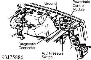
Fig. 14: Identifying Powertrain Control Module Location
TEST 18A - REPAIRING ARM SENSE CIRCUIT FROM REMOTE KEYLESS
ENTRY MODULE
NOTE: For connector terminal identification, refer to the CONNECTOR IDENTIFICATION table. For appropriate wiring diagram, see appropriate chassis wiring diagram in the WIRING DIAGRAMS section.
-
If malfunction is with disarm system, go to TEST 18B.
Disconnect Remote Keyless Entry (RKE) module. See Fig. 12 in TEST 3A.
Using DRB-II, check fused battery feed voltage at terminal "A" (Pink
wire) of RKE module connector. If less than 10 volts, repair open
fused battery feed circuit (Pink wire). Perform TEST VER-1. -
If voltage is more than 10 volts, check resistance of
system ground at terminal "H" (Black wire) of RKE module connector
using DRB-II. If resistance is more than 15 ohms, repair open system
ground (Black wire). Perform TEST VER-1. If resistance is less than 15
ohms, check resistance of arm sense circuit at terminal "F"
(Pink/Orange wire) of RKE module connector using DRB-II. -
If resistance is less than 5 ohms, repair arm sense
circuit (Pink/Orange wire) for short to ground. Perform TEST VER-1. If resistance is more than 5 ohms, connect jumper wire between fused battery feed terminal "A" (Pink wire) and arm sense terminal "F"
(Pink/Orange wire) of RKE module connector. If security light flashes, replace RKE module. Perform TEST VER-1.
4) If security light does not flash, disconnect VTA module.
Using external ohmmeter, check resistance of arm sense circuit.
Connect ohmmeter between terminal No. 6 (Pink/Orange wire) of VTA
module connector and terminal "F" of RKE module connector. If
resistance is more than 5 ohms, repair open arm sense (Pink/Orange
wire). Perform TEST VER-1. If resistance is less than 5 ohms, replace
VTA module. Perform TEST VER-1.
TEST 18B - REPAIRING DISARM SENSE CIRCUIT FROM REMOTE KEYLESS
ENTRY MODULE
NOTE: For connector terminal identification, refer to the CONNECTOR IDENTIFICATION table. For appropriate wiring diagram, see appropriate chassis wiring diagram in the WIRING DIAGRAMS section.
-
Determine if all courtesy, dome and cargo lights are
functioning properly. Repair interior lights that are not functioning
properly. -
Disconnect Remote Keyless Entry (RKE) module. See Fig. 12
in TEST 3A. Using DRB-II, check courtesy light control circuit voltage
at terminal "C" (Violet/Orange wire) of RKE module connector. If
voltage is less than 10 volts, repair open courtesy light control
circuit (Violet/Orange wire). Perform TEST VER-1. If voltage is more
than 10 volts, replace RKE module. Perform TEST VER-1.
TEST VER-1 - VERIFICATION TEST
-
Verify system operation. Ensure all doors, hood and
liftgate are closed. Open driver�s door. Remove ignition key from
vehicle. Lock all doors with power door lock switch. Close driver�s
door. If instrument panel theft alarm "SET" light flashed, system is
operational and verified. If "SET" light did not flash, 20 engine
start cycles have not occurred or theft alarm system is
malfunctioning. -
Determine if security light is flashing. If light is not
flashing, go to TEST 1A. If light is flashing, system is functioning
properly
REMOVAL & INSTALLATION
Information is not provided from manufacturer.
WIRING DIAGRAM
See appropriate wiring diagram in the WIRING DIAGRAMS article in the ENGINE PERFORMANCE section.
Source: https://jeep-manual.ru/index.php?page=281
0 Response to "2000 Cherokee Power Lock Orange violet No Ground Continuity"
Post a Comment